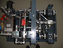
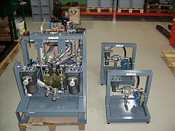
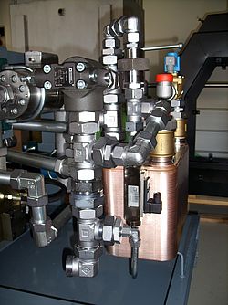
Custom solutions - a device for measuring hydraulic parameters


Suggested solutions are based on specific requirements of the Provider. The hydraulic scheme of the proposed solution is reminded by the Contracting Authority.
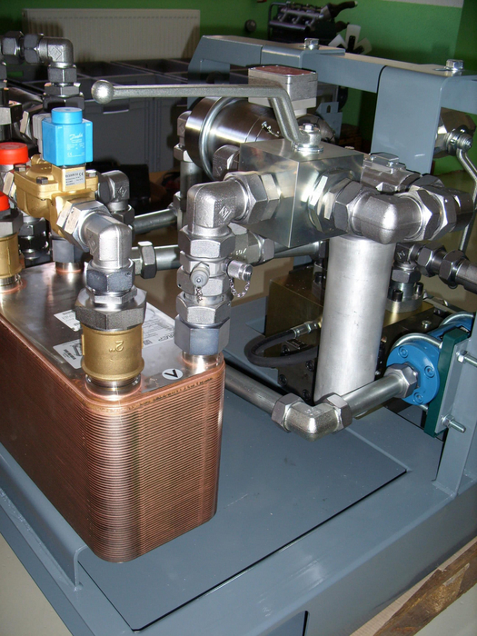
The choice of hydraulic elements is based on their required function, pressure resistance and with the utmost to minimize pressure losses in the hydraulic system. Selected hydraulic components are from renowned world manufacturers, ensuring their possible serviceability or modification. The flow, temperature and pressure sensors can be supplied, including the calibration protocol.
Provider defined operating parameters:
- Maximum flow: 300 l / min
- Maximum pressure: 450 bar
- Operating temperature range: 15 ÷ 100 ° C
- Oil viscosity range: 6.7 ÷ 76 cSt
- Maximum pressure loss in the circuit at 46 cSt and flow rate 150 l / min: 35 bar
- Outer dimensions: of europallets
- Possibility of transport with low-lift pallet trucks
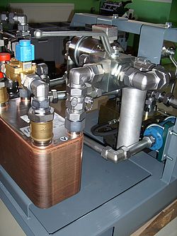
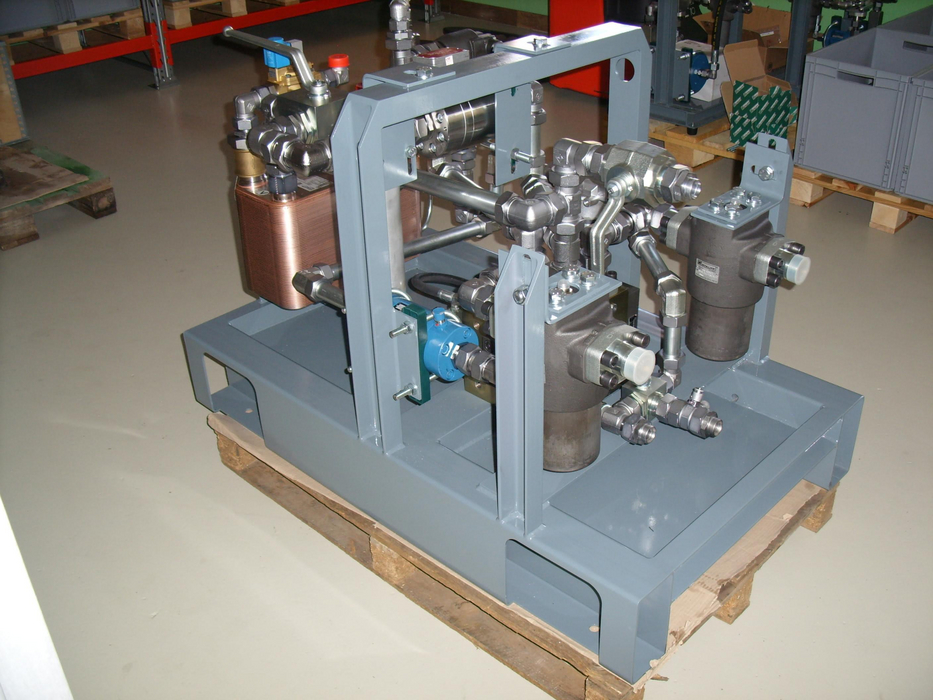
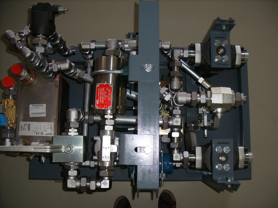
System Description:
The preparation is made up of a welded steel frame with an oil pan in which any hydraulic oil leaks are caught. Individual hydraulic elements are attached to the steel frame. Hydraulic connections are made by piping, which is supplemented by hoses. Part of the frame is hinged eye for the transport of preparations using a crane. The preparation is corrosion-treated with two-component polyurethane paint.
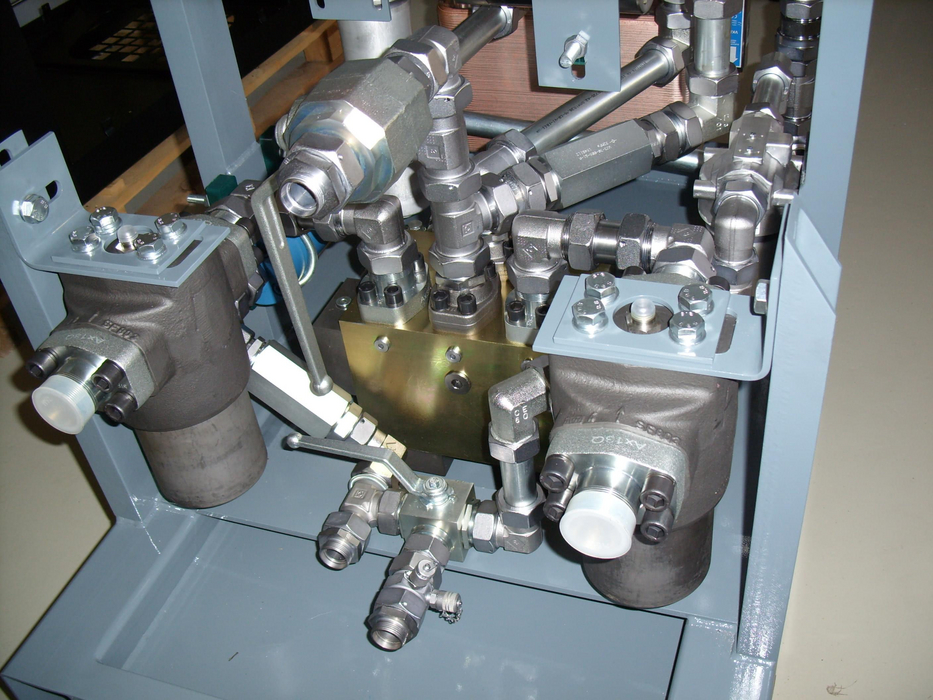
High-pressure part of the hydraulic system is designed to a working pressure of 450 bar and a flow rate of 300 l / min. The high pressure system consists of:
- High pressure hydraulic filters
- Rectifier and load block in bridge connection
- Electro-hydraulic proportional safety valve, which serves as the control stage
Low pressure part of the hydraulic system is rated at 63 bar and a flow rate of 300 l / min.
The low-pressure system consists of:
- 200kW water cooler
- filter
- volume spindle meter with sufficient impulses per liter to ensure the required accuracy of measurement
- measuring and controlling the temperature at the outlet of the radiator
- a three-way ball valve, which bypasses the flowmeter
- Two-stage safety valve and diaphragm cut-off as a pressure relief device for the low-pressure part
- a flow indicator to monitor possible oil leakage from the low pressure branch into the tank


Peter Lauko
Tel.: +421 37 7777 955
Mobile: +421 903 282 644
Fax: +421 37 7777 967
Email:lp@bibus.sk
Jaroslav Tvrdoň
Tel.: +421 37 7777 954
Mobile: +421 914 336 525
Fax: +421 37 7777 967
Email: tvr@bibus.sk
Vladimír Begáň
Tel.: +421 37 7777 954
Mobile: +421 914 336 527
Fax: +421 37 7777 967
Email:vbe@bibus.sk